Here we will introduce the key concepts of the AC metering unit as a system/product.
The purpose of this material is to introduce the key concepts, allowing a reader to venture into the ether and find more information on these topics themselves.
Voltage Sensing
Voltage sensing is the process of measuring the voltage between two points in an electrical system.
In single-phase AC metering, this is typically live to neutral and is known as phase voltage.
In multi-phase systems, it is common to measure line-to-line voltages, referred to as line voltages.
Generally speaking, the goal of the voltage sensing circuit is to:
- Scale the input mains voltage (e.g. 230 V RMS) to a safe and measurable level for the ADC.
- Maintain a linear, phase-accurate, and low-noise signal path.
By far the most commmon method for voltage sensing is to use a resistive (potential) divider to scale the voltage to a safe range for input to the ADC.
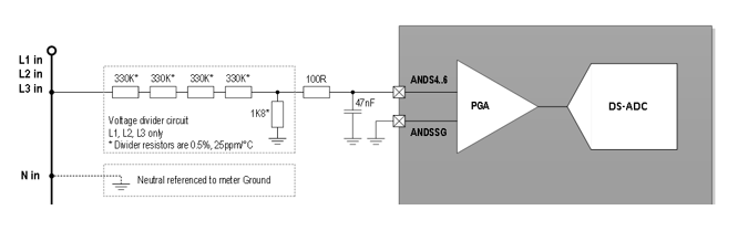
- Note
- With the AC signal centered around zero, a common set of errors can occur due to signal biases.
These biases can be introduced intentionally, such as using an ADC reference voltage (or Vref/2) as a bias point.
Or unintentionally, such as offset errors from PGA's (programmable gain amplifiers) or ADC's.
This is where filtering considerations are required to remove DC components from the signal
Generally speaking a HPF (high pass filter) will always be used to remove these DC components (biases) from the signal.
This actually becomes a design benefit because this allows a system, ADC or amplifier designer to allow a for poorer performance in bias/offset errors, understanding that in the end system these will be compensated for using a HPF.
This allows the design and selection of ADC's with accuracy focus on the areas that matter most, such as noise rejection.
Line Frequency
Line frequency refers to the fundamental AC system frequency, typically 50 Hz or 60 Hz, depending on regional standards.
Accurate line frequency measurement is important for:
- Power quality monitoring.
- Synchronisation of power measurements.
- Detection of abnormal supply conditions (e.g. under-frequency or over-frequency events).
Frequency is a quality indicator of the above grid health due to strict frequency gaurantees by national supply operators - for example the UK National Grid gaurantees +/-1% deviation from 50Hz, though normal operating conditions are often much more accurate.
This makes intuitive sense when thinking of the supply side, for example when a large generator gets overloaded its operation will slow or even stall - the speed of which is directly proportional to the frequency on the grid.
Therefore accurate frequency measurement is quite a common requirements, specifically noteable in EV chargers.
Current Sensing
Current sensing is the process of converting line current into a measurable voltage signal for the ADC subsystem.
The sensing element must provide a linear, phase-accurate, and low-noise representation of the true current waveform.
In this section we will look at common current sensing techniques in AC metering.
- Note
- Please also see the note on biases in the voltage sensing section, this also applies to current sensing.
Shunt
A shunt resistor is a precision low-ohmic resistor placed in series with the current path.
The voltage drop across the resistor is proportional to current by Ohm’s law:
\[ V_\mathrm{shunt} = I_\mathrm{line} \cdot R_\mathrm{shunt} \]
| Advantages | Disadvantages |
|---|---|
| - High accuracy and linearity - Excellent phase response - Low cost and simple to implement - Tamper resistant | - No galvanic isolation - Power dissipation increases with current - Must be placed carefully to avoid thermal drift and EMI coupling |
Shunts are most common in low-cost single-phase or direct-connected meters.
CT (Current Transformer)
A current transformer (CT) provides galvanic isolation between the line and measurement circuit.
It works on the principle of magnetic induction, where the line current through the primary winding induces a proportional current in the secondary winding:
\[ I_\mathrm{secondary} = \frac{I_\mathrm{primary}}{N} \]
Where \( N \) is the turns ratio.
This secondary current is then converted to a voltage through a burden resistor and filter network to be fed into an ADC.
| Advantages | Disadvantages |
|---|---|
| - Provides isolation and safety - Low insertion loss - Suitable for high-current applications | - Limited bandwidth and possible phase shift at low current - Requires burden resistor for voltage conversion - Potential for core saturation issues - Susceptible to tamper |
Rogowski Coil
A Rogowski coil is an air-cored current sensor that measures the rate of change of current:
\[ V_\mathrm{rogowski} = -N \frac{d\phi}{dt} \]
Where \( \phi \) is the magnetic flux and this can actually be rewritten as:
\[ V_\mathrm{rogowski} = - \frac{\mu N A}{2 \pi r} (\frac{dI}{dt}) \]
Where:
- \( \mu \) = Magnetic permeability
- \( N \) = Number of coil windings
- \( A \) = Area of the coil
- \( r \) = Distance from the conductor to the coil centre
- \( \frac{dI}{dt} \) = Rate of change of current
| Advantages | Disadvantages |
|---|---|
| - Excellent linearity and very wide bandwidth - No magnetic core (no saturation) - Provides galvanic isolation | - Output requires integration to reconstruct current waveform - Sensitive to positioning, meaning extra mechanical/assembly considerations |
Rogowski coils are often used in industrial meters or power quality analyzers where high accuracy and wide dynamic range are needed.
Power & Energy
Power and energy measurement combine the sensed voltage and current to compute instantaneous and averaged quantities.
Power computation involves:
- Instantaneous power: \( p(t) = v(t) \cdot i(t) \)
- Active power (P): real work done.
- Reactive power (Q): stored and released energy in inductors/capacitors.
- Apparent power (S): vector sum of P and Q.
Energy is obtained by integrating power over time:
\[ E = \int p(t) \, dt \]
Digital meters perform this discretely by:
- Sampling voltage and current.
- Computing instantaneous or average power.
- Converting to energy per sampling window.
- Accumulating energy over time.
- Storing (logging) and sharing (displaying/outputting) this data.
Pulse Output (Impulse)
Many meters include a pulse output (e.g. LED or open collector) proportional to energy consumed.
This pulse output rate is a defining feature of a meter and is generally stated on the meters label to enable readouts.
This feature is called the Meter Constant and is generally provided in imp/kWh.
If a meter has a constant of 1000 imp/kWh then for every 1000 pulses, 1kWh has been output - or in other words 1 impulse equals 1 Wh (or 3600 Ws) of energy.
Pulse outputs are:
- Useful for calibration and verification.
- Often used for communication with external monitoring systems.
- Typically generated based on active energy accumulation.
Import & Export
- Todo
- explain import and export energy
Topology
The topology defines how voltage and current sensing channels are connected to measure one or more phases of a system.
Single Phase
Used in most domestic installations.
Measures one phase and neutral pair; both voltage and current are sensed from the same line.
The phase is generally tapped of a larger utility three phase supply.
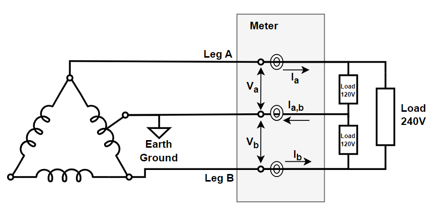
Split Phase
Common in North American systems.
Generally created when a utility supply phase (240V) is split using a centre tapped transformer.
This provides two 120V "legs" noted in the image as A and B, while the centre tap is connected to earth ground.
The loads are connected to either leg A or leg B, while larger domestic loads (ovens & washers etc.) are connected to the 240V load.
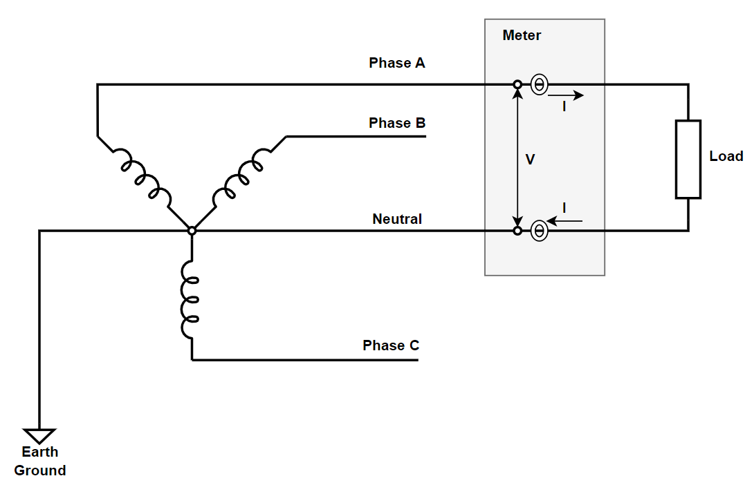
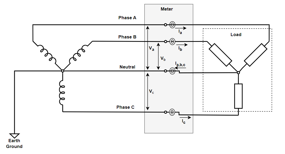
Three Phase
Used in industrial and commercial systems.
Involves measurement of three phase voltages and currents (generally with a neutral reference).
Supports:
- 3-wire (delta) and 4-wire (wye) systems (shown below is a wye connection).
- Independent per-phase energy accumulation.
Architecture Considerations
- Todo
- Explain consideration when constructing a meter (3PH arch vs 1PH arch - why 3PH shunt requires isolation etc.)
Meter Types
Meters are typically classified based on application and current rating.
Domestic
Designed for residential use, typically up to 100 A per phase.
Single-phase or split-phase configurations.
Often include communication (e.g. Modbus, M-Bus, or wireless).
Industrial
Used in three-phase installations with higher currents and voltages.
Support advanced features such as:
- Power factor monitoring.
- Harmonic analysis.
- Demand and load profiling.
Typical Classification Language
Meters are often marked with a current rating such as 230V 5(80)A 50Hz Class 1:
- The first value, 230V is the nominal operating voltage.
- The second value, 5, is the nominal current (In) which is often the current the meter is calibrated at.
- The value in brackets, 80, is the maximum current (Imax).
- The third value 50Hz is the target line frequency for which the meter is calibrated.
- The final note, Class 1, is the accuracy classification depending on standard for which compliance is being targetted.
This means the meter is accurate up to 80A, with calibration referenced at 5A, 230V & 50Hz achieving Class 1 accuracy.
Logging
Logging refers to the continuous or periodic storage of measured quantities (e.g. energy, voltage, current, frequency, temperature).
For billable meters logging is almost always a legal requirement.
Typical logging requirements include:
- Energy registers: total active/reactive energy per phase.
- Load profile: historical demand data.
- Event log: records of power loss, tamper events, or abnormal conditions.
Logging intervals can range from seconds to hours, depending on application requirements and available memory.
Calibration
Calibration is the process of adjusting the measurement system so that its readings accurately correspond to known reference standards.
In AC metering, calibration ensures that measured quantities such as voltage, current, power, and energy align with their true physical values across the meter’s operating range.
Calibration directly affects:
- Meter accuracy class compliance (e.g. Class 1, Class 0.5, Class 0.2S).
- Billing correctness and trust in the product.
- Regulatory certification and long-term stability.
Calibration Process
Calibration can be performed during manufacturing or field servicing.
It involves injecting known reference signals and adjusting the digital or analog correction coefficients so that the meter reports within tolerance.
Typical calibration stages include:
- Coefficient Calibration — Apply a precision source with simulated load conditions (e.g. 230 V RMS, 50Hz & 5A) and adjust scaling factors and coefficients for internal sampling chains (V, I, P, Q & S).
- Phase angle calibration — Ensure applying UPF (Unity Power Factor) signals so that any phase error present is detected and removed/compensated for internally.
- Energy integration check — Run a time-based test (e.g. 1 kWh reference load) to confirm cumulative energy accuracy.
Calibration Methods
Meters are often calibrated using one of the following methods:
- Single-point calibration:
Adjusts meter response at one nominal operating point (e.g. 230 V, 5 A, 50 Hz).
This is the ideal to save manufacturing costs. - Multi-point calibration:
Performs calibration at multiple voltage/current levels and frequencies to map linearity and temperature effects.
Produces higher accuracy and better performance over the full dynamic range, common in Class 0.5S or better meters.
Generally calibration is done on an automated rig in a high production volume environment where computer-controlled sources & reference meters (0.02% accuracy or better) generate precision load/operating conditions and trigger a calibration across a batch of meters who store the data in non-volatile memory.
Tampering
Tampering refers to deliberate or accidental actions that alter a meter’s intended measurement behaviour.
Detection and logging of tampering events are crucial for billing accuracy, safety, and regulatory compliance.
Common types of tampering include:
- Magnetic interference: applying strong magnets to saturate CT cores or affect magnetic sensors.
- Neutral disturbance: disconnecting or reversing the neutral path to influence current flow measurement.
- Phase reversal: swapping current transformer polarities or voltage phase wiring to reverse energy direction.
- Bypass connections: creating parallel paths around the sensing element (e.g. across shunt or CT secondary).
- Earth tampering: grounding one terminal of the current sensor to manipulate readings or cause leakage.
- Firmware/communication tampering: attempting to modify calibration data or meter configuration through communication ports.
Tamper Detection Techniques
Modern electronic meters incorporate multiple mechanisms to detect and record tampering:
- Reverse energy flow detection: identifies when power direction is opposite to normal consumption.
- Neutral missing detection: compares voltage and current vectors to infer open-neutral conditions.
- Magnetic field sensors: detect strong external magnetic fields near the metering enclosure.
- Phase angle monitoring: checks for unrealistic shifts between voltage and current vectors.
- Cover open / enclosure switch: triggers a hardware input when the meter cover is removed.
- Checksum and signature verification: protects calibration and configuration data against alteration.
When a tamper condition is detected:
- The event is timestamped and stored in the event log.
- A flag is raised in the meter’s register or communication frame.
- Optional relay or pulse output may be inhibited to prevent billing manipulation.
Tamper Logging
All tamper detections should be recorded in non-volatile memory, forming part of the legal metrology record.
Logged data typically includes:
- Event type (e.g. reverse energy, magnetic tamper, cover open).
- Date and time of occurrence and restoration.
- A running count or cumulative duration of tamper events.
These logs can be retrieved using protocols such as DLMS/COSEM, Modbus, or proprietary field tools for analysis and audit.
- Note
- Regulatory bodies (e.g. MID in Europe) require that tamper events cannot be deleted by normal user operation and must persist even after power loss.
This ensures traceability and accountability in billing-grade metering systems.
Isolation
- Todo
- Discuss isolation requirements where applicable
Compliance
Compliance in AC metering defines the set of standards, directives, and certification requirements that an energy meter must meet to be legally sold or installed in a given market.
It ensures the product meets technical performance, safety, electromagnetic compatibility, and accuracy criteria defined by national and international authorities.
- Warning
- This is not an exhaustive guide, it serves to gather information for reference.
To acquire meter compliance please seek consultation from appropriate authorities within the regions you are interested in selling.
Global Standards – IEC
At the highest level, global conformance is defined by the International Electrotechnical Commission (IEC) — a non-profit organization responsible for standardizing electrical and electronic systems worldwide.
IEC standards define what constitutes a compliant metering device from a technical standpoint and form the foundation upon which regional and national standards are based.
Common IEC standard families relevant to AC metering include:
| Category | IEC Series | Description |
|---|---|---|
| EMC | IEC 61000 | Electromagnetic compatibility (EMC) standards defining immunity and emission limits for electronic equipment. |
| General Metering | IEC 62052 | Defines general requirements for electricity metering devices (AC/DC systems). |
| Specific Metering | IEC 62053 | Defines accuracy and performance classes for static and electromechanical meters. |
| Manufacturing / Inspection | IEC 62058 | Defines methods for acceptance inspection and verification of newly manufactured meters. |
- Remarks
- IEC standards are the reference baseline; regional standards (e.g. EN 50470-3) are typically derived directly from them, sometimes with localized adjustments.
Regional / Bloc Standards (EU & UK)
Regions or trade blocs (e.g. EU, UK) translate international standards into legal frameworks that products must comply with to be marketed.
These frameworks define requirements — which are then supported by standards that provide the technical means to prove compliance.
Typical compliance hierarchy in the EU/UK:
| Step | Entity | Purpose |
|---|---|---|
| 1 | Requirements (2014/32/EU – MID / UK MIR 2016) | Defines legal and functional requirements for measuring instruments. |
| 2 | Standards (EN 50470-1, EN 50470-3) | Technical standards detailing design, accuracy, EMC, and environmental tests. |
| 3 | Testing (Accredited Test House) | Perform tests against standards to verify compliance. |
| 4 | Certification | Test house issues certification if requirements are met. |
| 5 | Declaration of Conformity (DoC) | Manufacturer issues DoC declaring the product compliant. |
MID / MIR Requirements
- EU MID (Measuring Instruments Directive – 2014/32/EU)
- UK MIR (Measuring Instruments Regulations – 2016)
These define the legal framework for electricity meters, specifying what must be tested, documented, and certified.
Testing is typically performed per BS EN 50470-1 and BS EN 50470-3.
EMC Requirements
- EU: EMC Directive 2014/30/EU
- UK: EMC Regulations 2016
While these are general EMC directives, specific test methods come from IEC 61000 series standards.
Meters are tested for:
- Conducted and radiated emissions
- Electrostatic discharge (ESD)
- RF immunity
- Burst and surge resilience
These tests confirm that the meter operates reliably in realistic electrical environments.
Accuracy Standards
Accuracy defines how closely a meter’s measurement corresponds to the true electrical quantity.
In the EU and UK, accuracy classes are defined under MID/MIR and EN 50470-3, while globally they trace back to IEC 62053.
| Region | Standard | Accuracy Classes |
|---|---|---|
| IEC | IEC 62053-21 / -22 / -23 | Class 2, Class 1, Class 0.5, Class 0.2S, etc. |
| EU / UK | BS EN 50470-3 | Class A, Class B, Class C |
Mapping between IEC and EN accuracy classes:
| EN 50470-3 (EU/UK) | IEC 62053 Equivalent | Relative Accuracy |
|---|---|---|
| Class A | Class 2 | Least accurate |
| Class B | Class 1 | Typical residential accuracy |
| Class C | Class 0.5 | High precision / industrial use |
- Remarks
- When designing meters, ensure calibration and testing are aligned with the target class for the intended region.
Compliance Path (EU/UK)
To achieve compliance, a typical AC energy meter must be verified against multiple domains of standards:
| Category | Examples / References |
|---|---|
| Accuracy / Metering | EN 50470-1 / EN 50470-3, IEC 62053-21, IEC 62053-22 |
| EMC | IEC 61000-6-1 / 6-2 (immunity), 61000-6-3 / 6-4 (emission) |
| Mechanical, Safety & Environmental | IEC 62052-11 / 31 (general & safety) |
| Manufacturing / Inspection | IEC 62058-11 / 31 (factory acceptance & inspection) |
- Remarks
- Compliance documentation must include test reports, calibration certificates, and the manufacturer’s Declaration of Conformity (DoC) citing all applicable directives and standards.
Useful References
- IEC: IEC Home
- CENELEC: CEN-CENELEC
- MID Directive: 2014/32/EU – EUR-Lex
- UK MIR: Measuring Instruments Regulations 2016
- BSI: BSI – Standards and Compliance